CamBam V1.0 and use of the 4th rotary axis.
Basically, CamBam is not designed to be used in 4-axis machining, but with some manual "additions" in the machining operations and some plugins, it is possible to use it for machining with one A or B rotary axis.
CamBam files as well as 3D objects are available in this archive
1. Positional machining.
a) Simple positional machining.
The principle is simple, the rotary axis only serves to position the part at a desired angle, then locks in position; then we can machine in XYZ as usual.
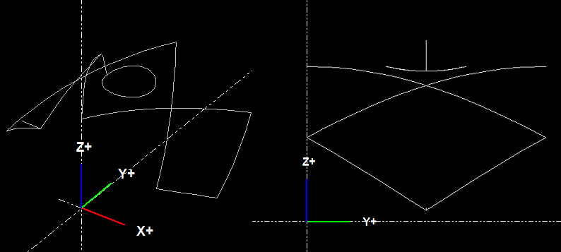
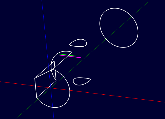
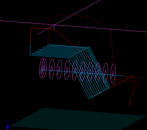
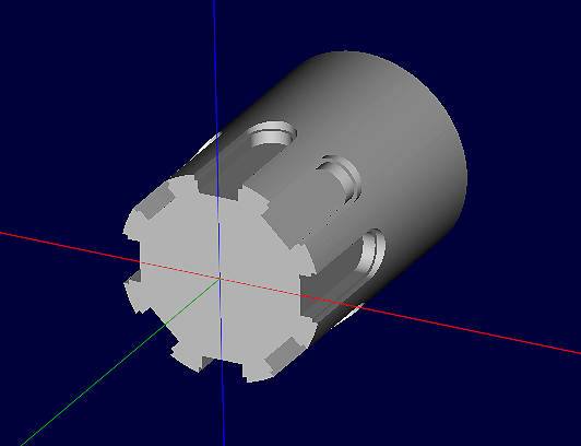
An example with the following part:
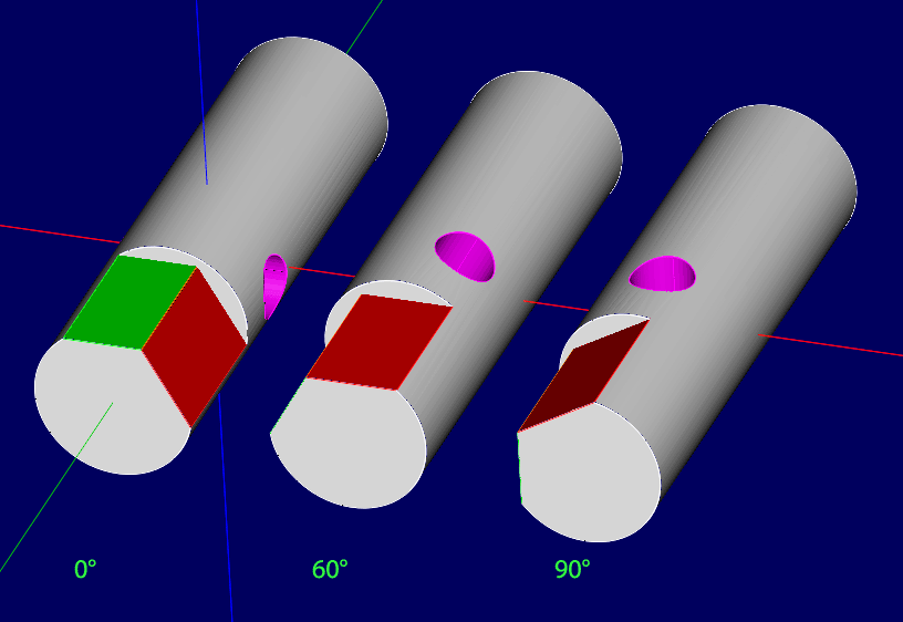
We will start with the rotary axis at 0° and we will machine the green area ; in this case a simple surfacing can be done with a pocket or profile operation.
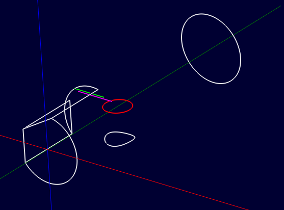
We will then rotate the rotary axis by 60°, then we will surface the red area in the same way.
And finally, we will rotate the axis another 30° to reach the 90° position and we will use a drilling operation to machine the hole.
The rotation information will have to be added manually in the machining operations concerned. We will see later how to do it.
Note that the 3D object is only there to make things more readable ; in reality it is not necessary until 3D profiling operations are used.
This method can be used with all types of machining operations, including 3D machining operations: in this case it will of course be necessary to have a 3D model and it will be possible to use the method of double-sided machining of 3D machining operations to make the top/bottom faces.
b) Positional machining with repetitions
In the previous case, each machining is different, whether by its type (surfacing, drilling), its machining parameters (the depth to be machined is not the same on the green face and the red face) and the angle positioning is not repetitive, which makes it necessary to define a specific rotation for each machining.
One can however have a part on which one wants to repeat the same machining in a regular way on the periphery of the part ; example machining a 6-sided or a splined shaft. In this case, there will be one or more machining operations (surfacing, pocket, drilling, or even 3D machining, etc.) repeated 6 times at 60° intervals for a 6-sided. We will then use the CamBam nesting function to repeat the machinings to which we will add an axis rotation command. (a rotation value relative to its last position).
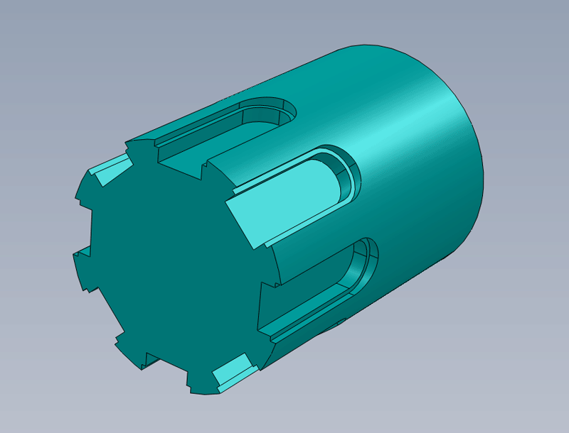
Example of a part that can be made by repetition at regular angular intervals. (here every 45°)
Note that these two methods can also be used with a non-motorized 4th axis; in this case it will be up to you to turn and lock the 4th axis to its new machining position ; it will suffice to insert an M0 (pause) in the Custom MOP Footer property of the last machining operation to stop the machining so you can turn the axis to its new position befor to continue the machining.
2. Wrapping GCode
a) Simple engraving
Another method, suitable for other types of machining, consists of working "flat", in other words, from CamBam's point of view, the machining is done in XYZ, then one of the coordinates X or Y, depending on the orientation of the 4th axis on the machine, is converted into an angular position. It's like wrapping the machining around a cylinder. On CamBam V1.0, the post-processor will convert the X or Y coordinates into A or B coordinates.
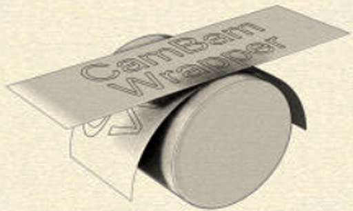
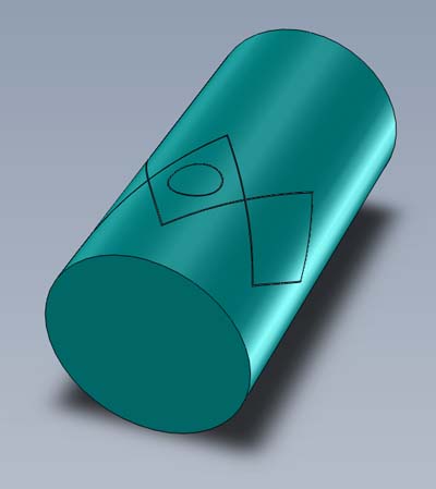
An example with text written "flat" and then wrapped around a cylinder.
In this case, the GCode produced is a simple 3-axis XYZ GCode, once produced, the GCode then undergoes a modification to convert the cartesian coordinates of the X or Y axis into polar coordinates for an A or B axis. This conversion can be done using a plugin (Wrapper), or if you are using version 1.0 of CamBam, it can be done directly by the post processor (which must have been selected for this).
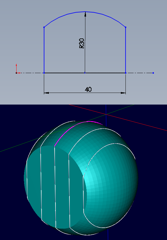
Example, engraving of a simple logo on a 40mm diameter cylinder.
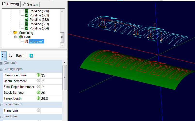
The "flat" toolpaths in CamBam.
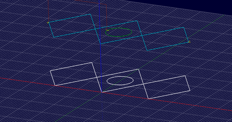
Note that the toolpaths are at radius in Z (blue toolpath), the drawing itself is at Z=0; it is important with the CamBam built-in engraving opeation.
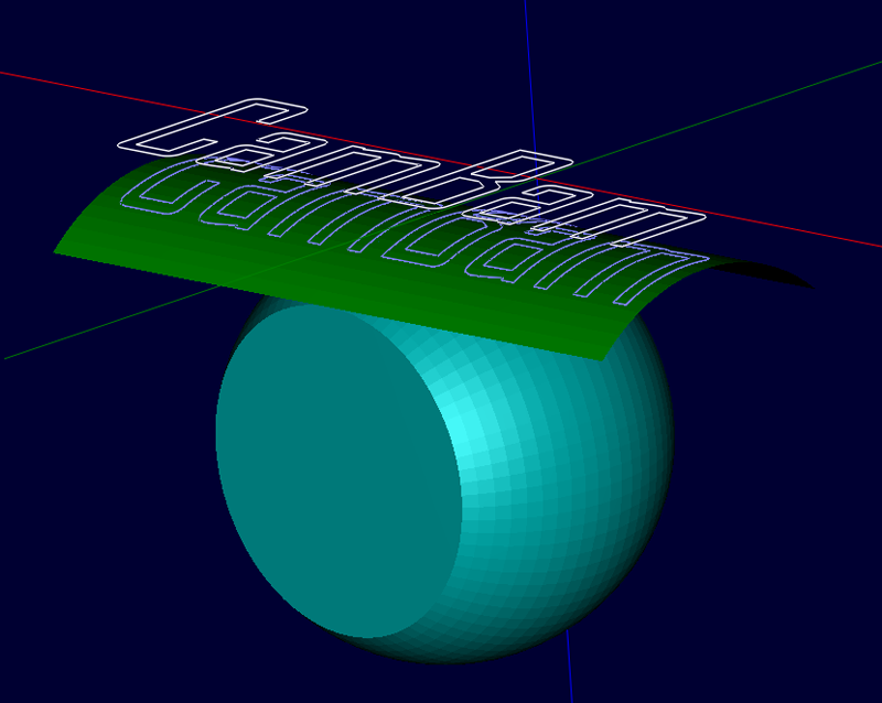
Once the GCode is done and wrapped, we get this result.
All types of machining operations can be wrapped.
Engraving and 3D machining operations will need to take into account their specificities, in particular the way the Z is managed in engraving (*), which differs from other machining operations.
(*) With the engraving operation, the Z coordinates for Stock surface and Target depth are relative to the Z position of the lines to be engraved and are not given in absolute coordinates as in other operations. I'm talking about the standard CamBam engraving operation ; the V-Engrave plugin works like other machining operations, ie. the Z position of the lines to be engraved has no effect, the values of Stock surface and Target depth are in absolute coordinates.
With CamBam V1.0 and wrapping via the post-processor (RotaryY or RotaryX), it is the Stock surface value that is used to define the wrapping radius, with the engraving operation it is therefore necessary that the drawing be at Z=0 and that Stock surface = the radius because unlike other machining operations where the value of Stock surface is an absolute value, independent of the Z position of the drawing, this is not the case with engraving where the value of Stock Surface is relative to the Z position of the drawing.
b) GCode wrapping used with 3D machining operations.
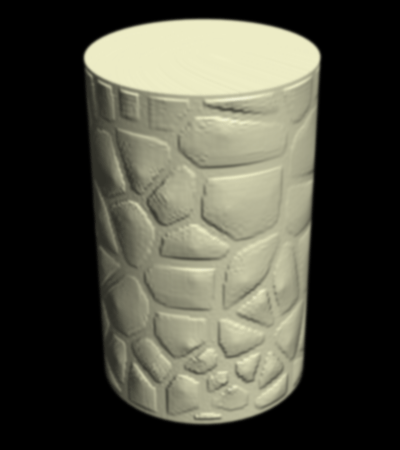
It is also quite possible to wrap 3D machining operations, such as this column which can be obtained following a wrap of a 3D profiling operation on a surface object (a mesh) representing a 3D stone texture.
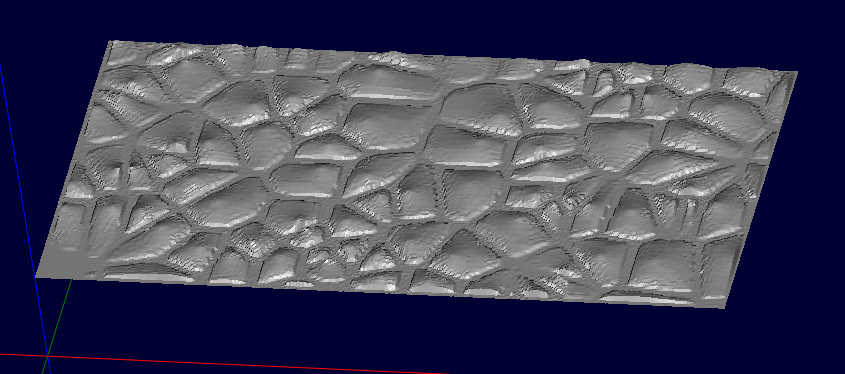
The 3D texture above was made in CamBam using the Voronoi Builder plugin, which allow the creation of 2D cells (stones) as below
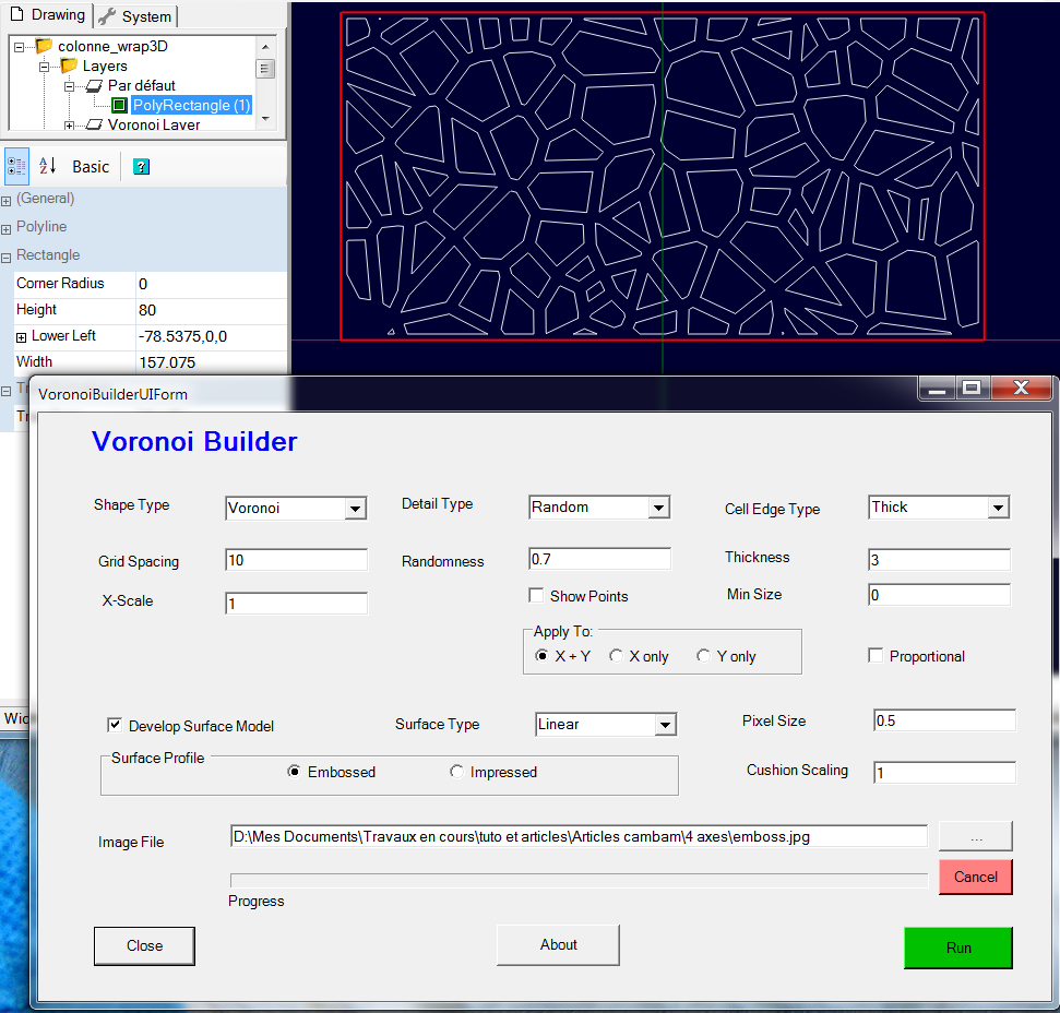
Then I used "Develop surface model" in the plugin, to generate the grayscale image below, representing a relief with bulging areas at the "stones".
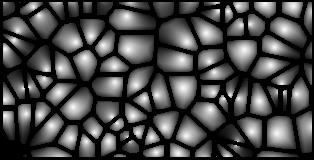
This image was then used to produce the 3D surface using: Draw/Surface/From Bitmap.
Here, we start from an already "flat" (unrolled) 3D shape, but if we have a "normal" 3D object, it will be necessary to unroll it in order to obtain the surface that will be used with the 3D machining operations
This unrolling of the source object can be done using my plugin Unroll 3D model.
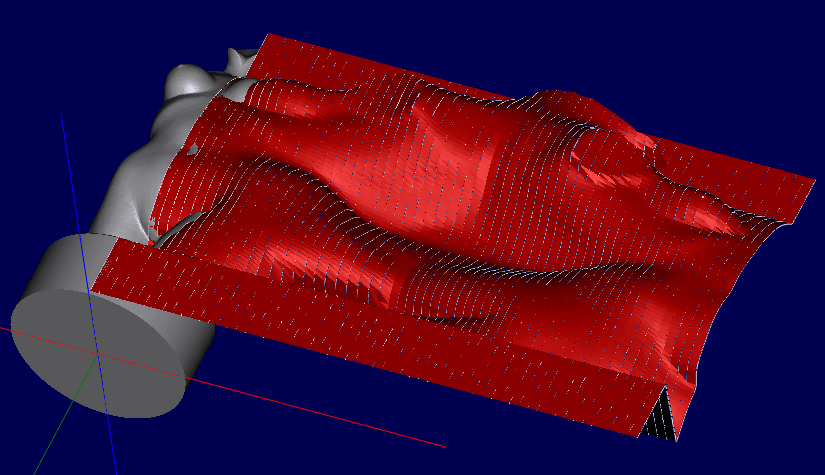
Here, the Venus statuette (in grey) has been unrolled to obtain the unrolled shape in red.
One or more 3D machining operations can be applied to the unrolled shape, then the GCode obtained will then be wrapped for machining with the 4th rotary axis.
See HERE for the plugin allowing to unroll a 3D object, as well as its documentation.
3. Practical examples
a) Simple positional machining
We are going to create the machining operations to create the three machining on the part below.
Opening and positioning the 3D object
This tutorial assumes that the Numerical move/rotate plugin is installed.
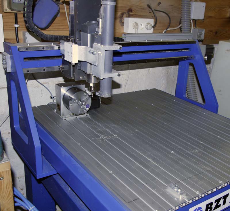
It is based on an A axis aligned with the Y of the milling machine.
The Z zero must be done at the rotation axis of the 4th axis.
The 4th axis installed on my machine, aligned with the Y axis
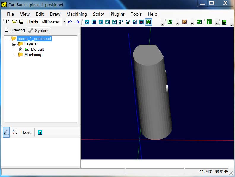
Open the Piece_1_positionel.stl file contained in the archive.
The surface object obtained will have to be positioned correctly because it is badly oriented.
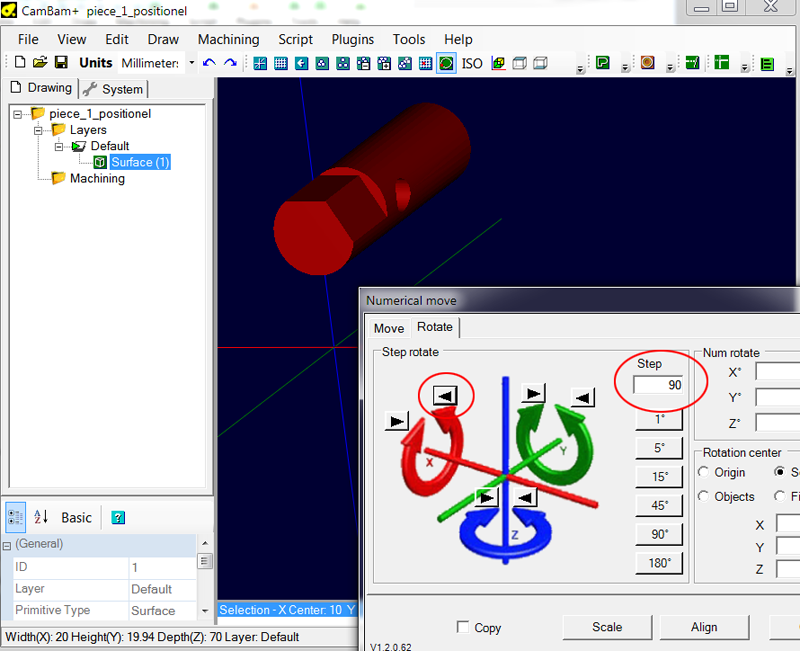
Select the surface object, open the Numerical move/rotate plugin (ctrl+shift+M) and rotate the object 90° around X counter-clockwise to get the following result.
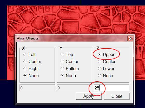
Then click the Align button to open the alignment tool and adjust the settings as pictured, then click Apply to position the 3D object.
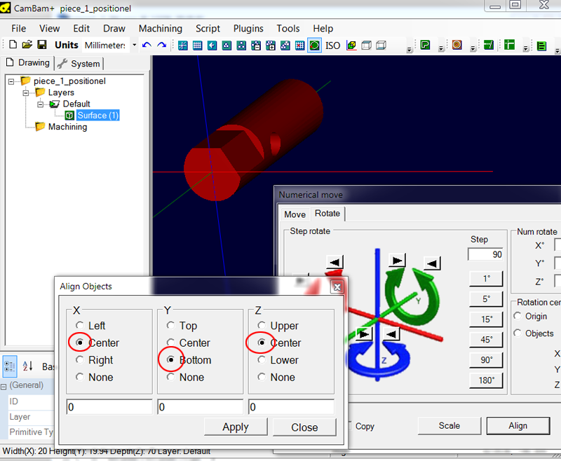
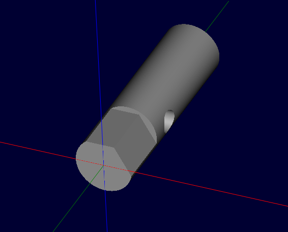
It should now be centered in Z and X, and the front face should be aligned with the 0 in Y as shown below.
Obtaining 2D lines for machining
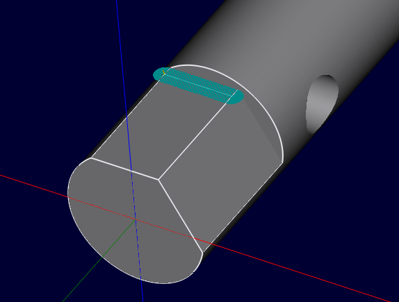
We are now going to create the 2D line that will be needed for machining the flat area ; This machining will be done with a profile operation + Cut Width enabled.
If you are using CamBam version 1.0, just use object snapping to be able to draw a line directly on the 3D object (green line in the image below). If you are using an older version, you will need to go through the intermediate step below.
Create a new layer (here Layer1), select the surface object, then use the Edit/surface/edge detect menu. You should get this result.
I have highlighted in green the line that interests us.
From there, the goal is to recover the green line alone. If drawn on CamBam V1.0 with object snapping, it's already done. Here, I will simply break down the polylines that make up the contours and retrieve only the line that interests me, but I could also draw the line directly since now, thanks to edge detection, I can snap to the ends of line.
I chose to show you the most complex way, because if here, we just have a straight line, we could have a more complex outline, and in this case, it is easier to recover an existing line than to create a new one.
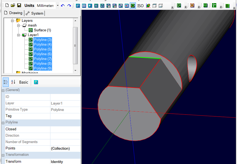
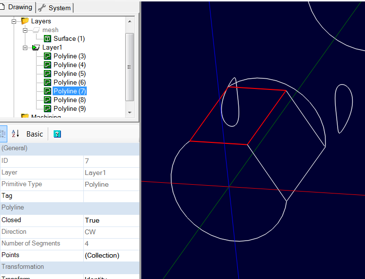
To clearly see what the lines in question look like, you can hide the layer on which the 3D object is located to see only the lines; as we can see, polyline 7 contains the line we are interested in.
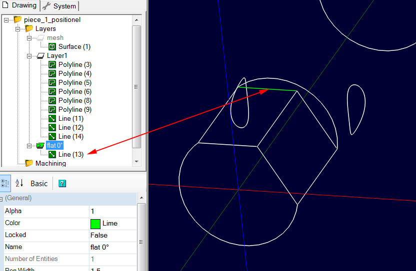
I will now explode (Edit/Explode) polyline 7 and keep only the line that interests me, which I would put on another layer called "flat 0°"; the other lines will no longer be used and can be deleted.
To put line 13 obtained after exploding on the new layer, just drag/drop it in the tree structure.
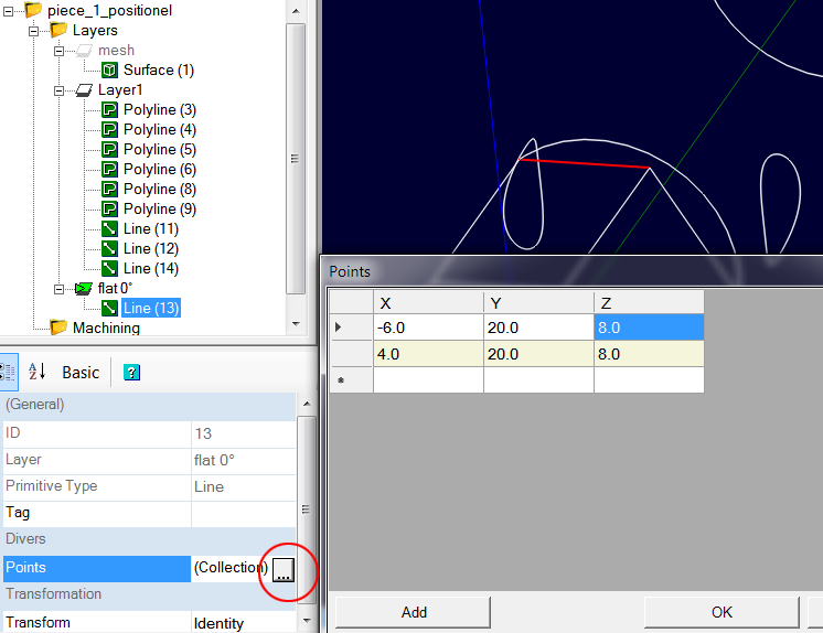
This line will not only be used to define the machining position, but it will also allow us to know the Z position of the flat area to be machined.
To know its Z position, select line 13, then click on the |...| of the Points property of the line. As we can see, the surface is at Z = 8
The part is 20mm in diameter, the upper surface of the cylinder is therefore at Z = 10
Setting up of the first machining operation.
We are now going to create the Profile operation which will allow us to surface the first flat area.
Select the line we created (Line 13 in the case of the example) then assign it an Profile operation.
Set the following properties as follows:
- Tool Diameter = 3
- Tool Profile = End Mill
- Stock Surface = 10 (the radius)
- Target Depth = 8
- Clearance Plane = 15
- Depth Increment = 2
- Milling Direction = mixed
- Adjust the other properties such as Cut Feedrate, Spindle Speed, etc to suit the material you are machining and the performance of your machine.
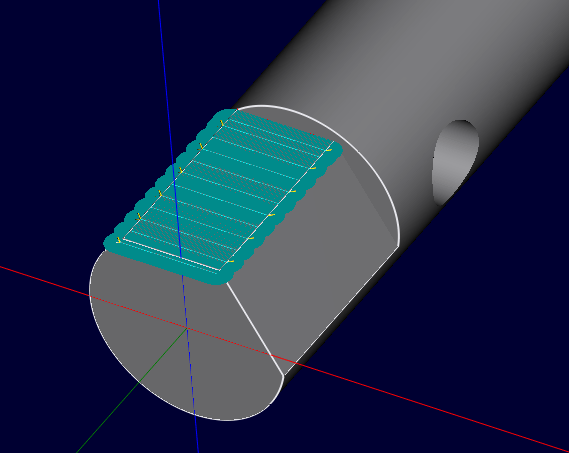
Activate the display of the cutting width (View/Show cut width)
Generate the toolpaths for this operation.
You should get the following result
If the machining is not done on the right side of the line, invert the value of the Inside/Outside property and regenerate the toolpaths in order to have the machining on the right side.
It only remains to give a value for Cut Width ; in this case, the flat area is 20mm long, we are going to give a slightly larger value so that the cutter does not cut the entire pass width at once; enter 22 for Cut Width then regenerate the toolpaths. You should get the following result:
We are done with this operation for now, save your work before to continue.
Setting up the second machining operation
We will repeat the same process to create the second flat area.
We are going to rotate the contour lines of layer 1 to put them in the new position.
- Hide the layer that contain the 3D surface object, it is not nedeed that the 3D object is rotated too because now we will only use the lines that we have obtained with Edge Detect.
- right-click layer 1 and choose Select All on Layer from the context menu to select all contour lines.
- Using the Numerical Move/Rotate plugin, rotate the contour lines selection 60° left around Y (CCW) to bring the 2nd flat area to horizontal.
- To have a clearer display, deactivate the previous machining operation (right click on the machining operation > Enable/Disable MOP)
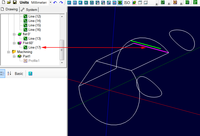
From there, do the same manipulation as before to retrieve the line that interests us and place it in a layer that we will call "Flat 60°"; we get the line in purple on the image. (line 17)
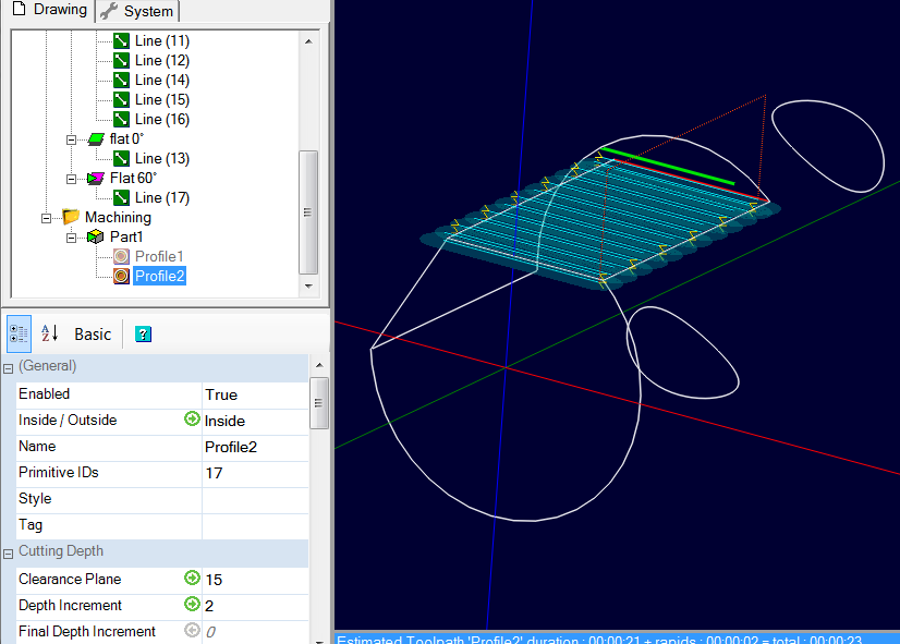
Copy/Paste the Profile1 operation, then assign line 17 to this new operation (by dragging and dropping line 17 onto the Profile 2 operation, or using the context menu of the Profile 2 machining operation: Select drawing objects)
Activate the Profile 2 operation, and change Target Depth to match that of the flat area ; here 7.464 and generate the toolpaths. If the cut is not on the right side, invert the value of Inside/Outside.
You should get the following result
Setting up the third machining operation
We will now machine the hole using pocket machining.
- Disable Profile 2 to get a clearer display.
- Select all the content of layer 1 (the outlines)
- Using the Numerical Move/Rotate plugin, rotate the contour selection 30° left around Y (CCW) to bring the hole into a vertical position.
You should get the following result.
Select the top circle, then use the Edit/Polyline/Arc Fit menu with a value of 0.02 ; This will create a "flat" circle made of arcs from the selected shape. Note that the shape is positioned at Z=0 ; it does not matter.
As before, create a new layer, which we will call "Hole" and move the circular polyline we just created there. We can now delete or hide layer 1; the outlines will no longer be useful to us.
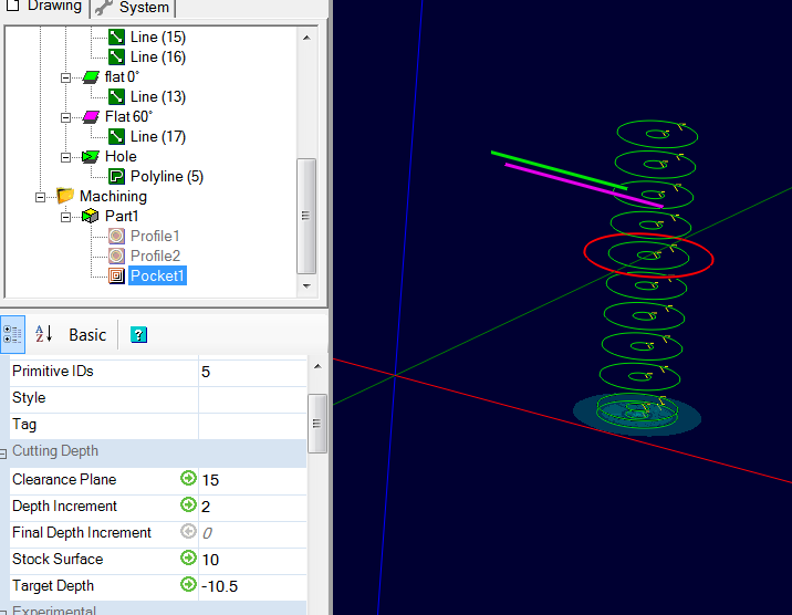
- Select the polyline we just created, then assign it a Pocket operation.
- Right click on profile 1 (or Profile 2) > Copy.
- Right-click on the pocket operation we just created > Paste Format to copy the settings from profile 1 operation into the pocket operation.
- Enable pocket operation and change Target Depth to -10.5
- Generate toolpaths
We are done with the machining operations.
Implementation of the 4th axis rotation instructions
We are now going to insert the codes which will make it possible to rotate the 4th axis to position it before each machining.
To do this, we will directly write the GCode instructions by hand in the machining operations Custom MOP Header property.
Activate the Profile 1 and Profile 2 operations which are currently inactive if you have followed this tutorial to the letter.
The GCode of the examples was produced by the Mach3 post-processor provided with CamBam, if you use another post processor, the GCode may have some variations.
Note that the direction of rotation under Mach3 is positive clockwise and negative counterclockwise.
In the case of this example, as we are rotating the part counter-clockwise, it will therefore be necessary to provide negative rotation values so that the display is in the right direction on Mach3.
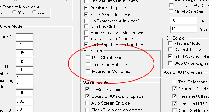
My settings in Mach3 are:
Menu Config/General Config
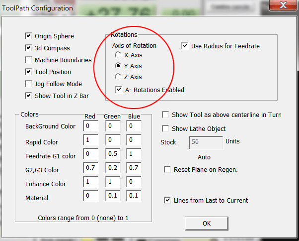
Menu Config/ToolPath for an A axis aligned with the Y axis
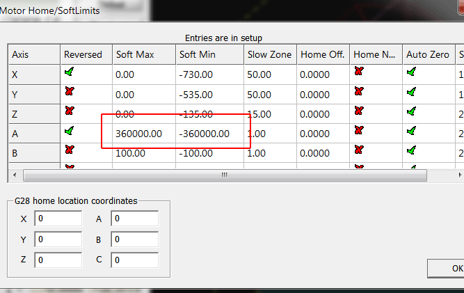
Menu Config/Homing-Limits (allows 1000 turns in positive and negative)
If we generate the GCode directly, without having put the rotation instructions, we will obtain the following result:
( Made using CamBam - http://www.cambam.co.uk )
( positionel_simple 8/29/2019 9:37:52 PM )
( T5 : 3.0 )
G21 G90 G91.1 G64 G40
G0 Z15.0
( T5 : 3.0 )
T5 M6
( Contour1 )
G17
M3 S12500
G0 X-6.0 Y-0.5
G0 Z11.0
.....
.....
G1 F600.0 Y18.5
G1 F800.0 X-6.0
( Contour2 )
S12500
G0 Z15.0
G0 X6.6549 Y-0.5
G0 Z11.0
.....
.....
G1 F600.0 Y18.5
G1 F800.0 X6.6549
( Poche1 )
S12500
G0 Z15.0
G0 X0.29 Y29.3642
G0 Z11.0
G1 F600.0 Z8.0
G3 F800.0 X0.6268 Y30.3108 I-0.3276 J0.6498
.....
.....
G3 X1.1003 Y27.7569 I-1.0237 J2.3111
G0 Z15.0
M5
M30
To insert the rotation instructions, we'll use the Custom MOP Header property of each operation that requires positioning the A axis at a given angle, and insert the following GCode into it:
G0 Z15
G0 A-xx
The G0 Z15 raises the Z in rapid to position 15 so the tool is in safe position
The G0 A-xx rotates the A axis to the angular position -xx°
It is possible to replace the G0 Z15 by a macro which will directly return a G0 to the clearance plane and which will use the value of the Clearance Plane property of the machining operation.
For example, to raise the Z axis to the current clearance plane and rotate the A axis to the -60° absolute position I would write
{$clearance}
G0 A-60
The {$clearance} macro will return G0 Z15 in the case of this example.
Note that this macro will only produce a G0 Zxx if necessary, ie. if the tool is not already at the clearance plane or above.
It is vital to program this Z move to the clearance plane, either by a G0 command or via the macro, otherwise the A axis risks rotating before the tool is outside of material.
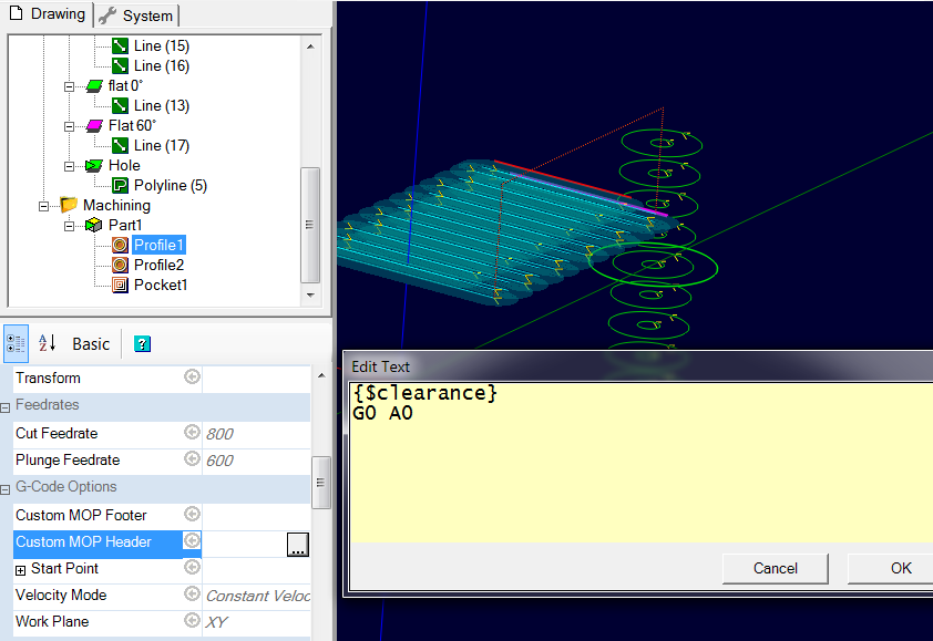
Select the profile 1 machining operation, then click the |...| button of the Custom MOP Header property ; in the edit window, enter the following text then click OK to validate.
{$clearance}
G0 A0
Select the Profile 2 machining operation and enter the following text in the Custom MOP Header property
{$clearance}
G0 A-60
And finally do the same for the Pocket 1 operation and enter the text:
{$clearance}
G0 A-90
Save your project then generate the GCode for the whole project ; you should get the following result where you can see that the rotation instructions have been added.
( Made using CamBam - http://www.cambam.co.uk )
( positionel_simple 8/29/2019 10:12:08 PM )
( T5 : 3.0 )
G21 G90 G91.1 G64 G40
G0 Z15.0
( T5 : 3.0 )
T5 M6
( Contour1 )
G17
G0 A0
M3 S12500
G0 X-6.0 Y-0.5
G0 Z11.0
G1 F600.0 Z9.0
.....
.....
G1 F600.0 Y18.5
G1 F800.0 X-6.0
( Contour2 )
G0 Z15.0
G0 A-60
S12500
G0 X6.6549 Y-0.5
G0 Z11.0
G1 F600.0 Z9.0
G1 F800.0 X-4.9282
.....
.....
G1 F800.0 X6.6549
( Poche1 )
G0 Z15.0
G0 A-90
S12500
G0 X0.29 Y29.3642
G0 Z11.0
G1 F600.0 Z8.0
.....
.....
G3 X1.1003 Y27.7569 I-1.0237 J2.3111
G0 Z15.0
M5
M30
On the CamBam display, all the operations remain superimposed because the software does not know how to display angular positions, but on a simulation under Mach3, we can clearly see that the different operations are performed at the correct angular position.
If it is necessary to perform several operations in a row at the same angular position, then of course only the first operation at this angular position will have to contain a rotation order.
The CamBam example file is available in the archive under the name: positionel_simple.cb
b) Positional machining with repetitions
Open the canelures.stl 3D object, then, if necessary, rotate it and position it so as to align it with the Y axis and to put its front face at 0 in Y using alignment functions such as we have already done this for the previous piece.
Getting 2D lines for machining
We will now extract the outlines to a new layer.
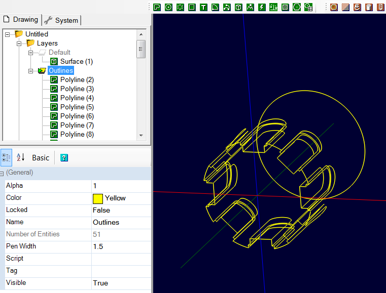
Create a new layer called "Outlines" (for example), then select the 3D object and use Edit/Surface/Edge detect.
Here, the layer containing the 3D object is hidden in order to better see the resulting lines.
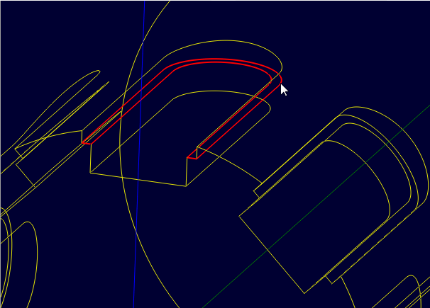
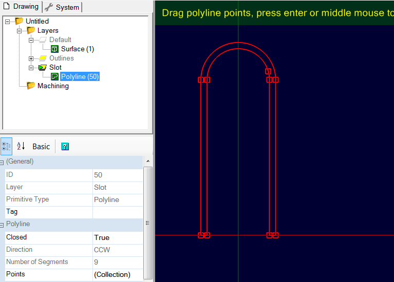
On the top slot, we'll select the polylines that will give us the outline of the wide slot and the outline of the narrow slot ; the height position of the polylines does not matter ; in this specific case, the easiest way is to select the polyline shown in the following image because it contains the 2 contours that interest us in the same polyline.
Create a new layer called "Slot" (for example), select the polyline and move it to this new layer.
Hide or delete the "Outlines" layer which will no longer be useful to us.
Switch to plan view (XY plane) with an ALT + double left click in the drawing window (or via the "views" toolbar if it is installed), then double click on the polyline to switch to edit mode. As you can see in the image, because the path was extracted from a mesh object, you don't get an arc on the rounded parts, but a succession of small segments.
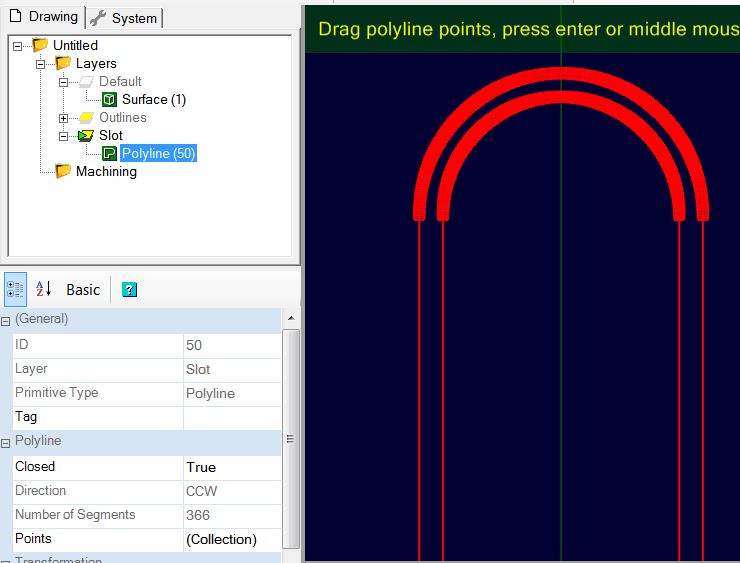
With the polyline selected, use Edit/Polyline/Arc Fit with a tolerance of 0.02 (mm)
We then obtain a result as below.
Also note that the polyline has been aligned with the 0 in Z.
Of course, it would have been possible to draw these polylines directly in CamBam, it would even have been easier.
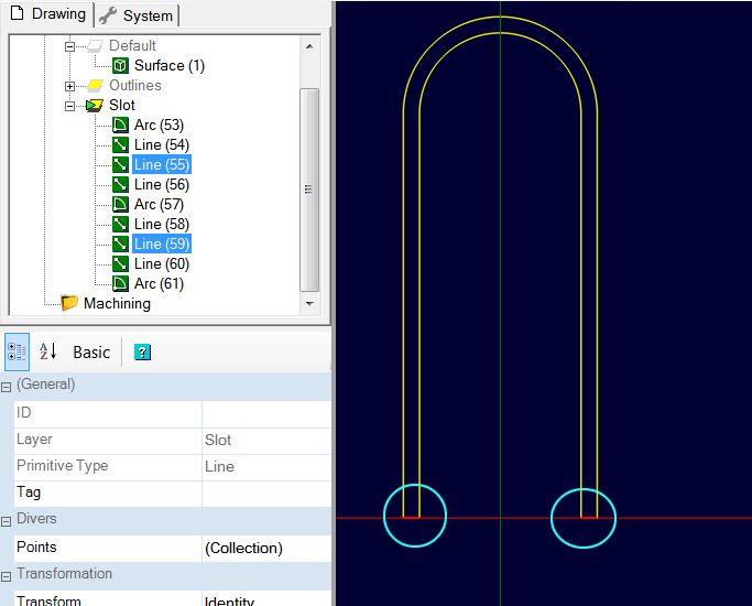
To do the machining, we need to separate the 2 polylines, and extend them a little downwards, so that the tool can go down out of the material. We also need to delete the 2 small segments at the bottom, which join the 2 outlines.
Select the polyline, then use the Edit/Explode menu to obtain the polyline components.
Select the 2 bottom lines (circled in blue on the image) and delete them.
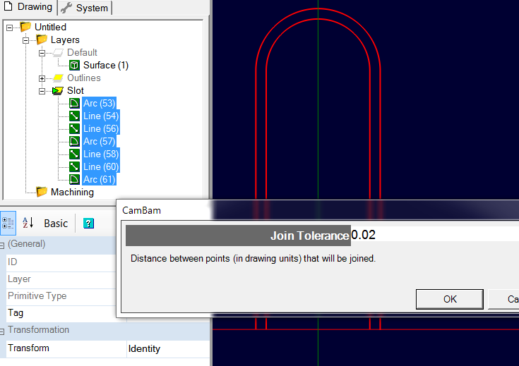
Then, select all the objects of the "Slot" layer then use the Edit/Join menu with a tolerance of 0.02 to reconstitute 2 complete polylines.
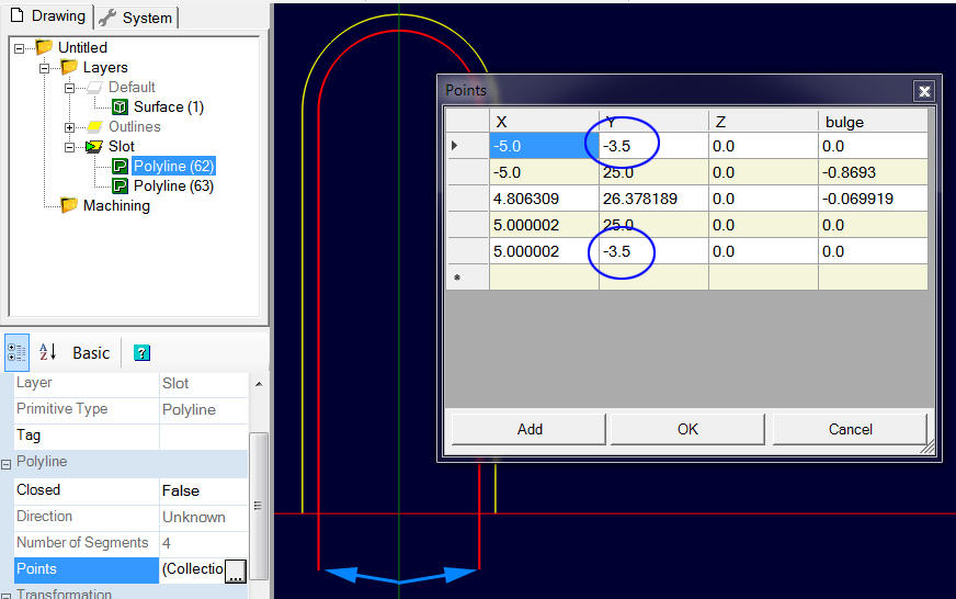
We are now going to extend the 2 polylines downwards ; in this case, the easiest way is to edit the collection of points of each polyline and to modify the value of the 2 points which are aligned on the X axis ; their Y coordinate is 0 ; we will change it to -3.5 in Y.
For each of the two polylines:
- select it
- click the |...| to the right of the Points property, and change the values that are 0 in Y to a value of -3.5
- confirm with OK
Once the two polylines have been extended, we will now be able to add two machining operations to make the two slot levels. As before, we will use a Profile operation with a Cut Width value <> 0 if necessary.
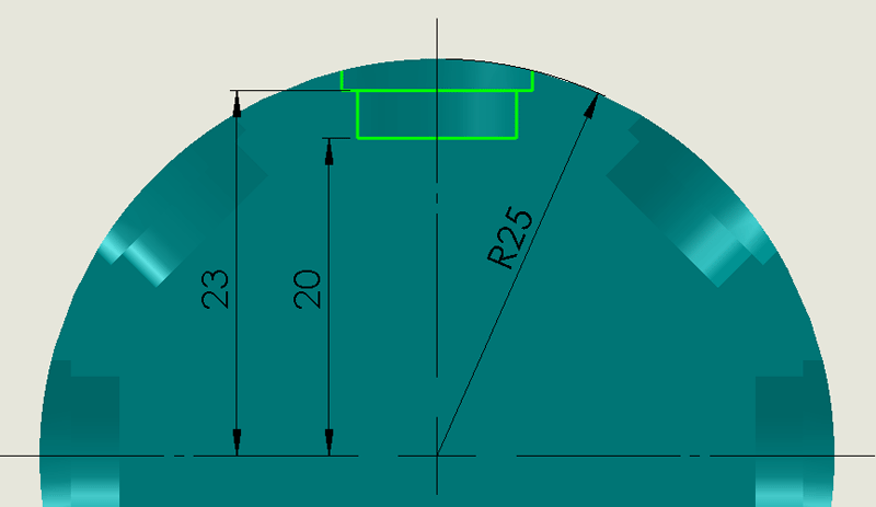
Here are the dimensions of the part:
Setting up of machining operations
We will start by machining the deep groove using the inner polyline, then using a second machining operation we will machine the rabbet at the top of the groove using the outer polyline.
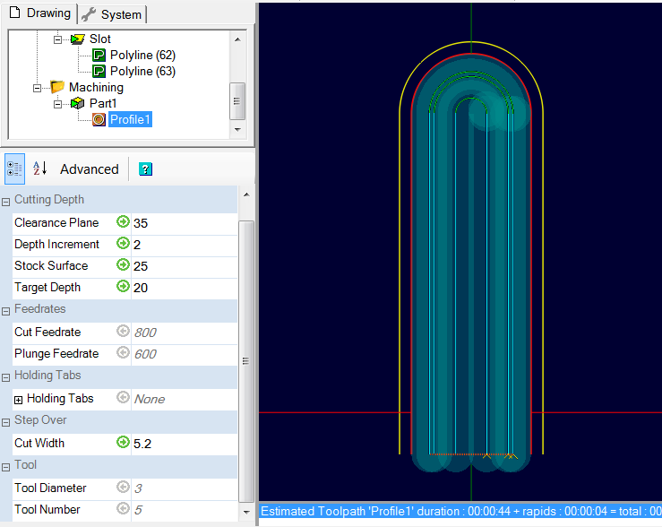
Select the inner polyline, then assign it a Profile machining operation with the following settings:
- Tool Diameter = 3
- Tool Profile = End Mill
- Stock Surface = 25 (the radius)
- Target Depth = 20
- Clearance Plane = 35
- Depth Increment = 2
- The groove being 10mm wide, set the Cut Width to 5.2 for example, to have an overlap of the passes in the center.
Adjust the other properties such as Cut Feedrate, Spindle Speed, etc. to suit the material you are machining.
Activate the display of the cutting width (Menu View/Show cut widths)
Generate the toolpaths for this operation.
You should get the following result in top view ; if the machining is not done on the right side, modify the Inside/Outside property (on an open line, the machining side depends on the drawing direction of the polyline)
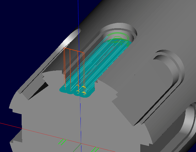
And in perspective view, you can see that the machining is done at the right position and at the right depth by displaying the layer containing the 3D object.
Select the outer polyline, then assign it a Profile machining operation with the following settings:
- Tool Diameter = 3
- Tool Profile = End Mill
- Stock Surface = 25 (the radius)
- Target Depth = 23
- Clearance Plane = 35
- Depth Increment = 2
- Cut Width = 0
Generate the toolpaths and you should get the result below.
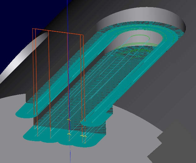
We are done with setting up the machining operations.
Setting up rotation and repeat instructions
We are now going to set up the rotation instructions as well as a machining repetition in order to reproduce these two machining operations eight time with a 45° offset.
In the case of simple positional, we wrote the rotation instructions in the machining operations, and this for each machining position, and these instructions were in absolute position. (0°, -60°, -90°)
In the present case, on the other hand, we are going to repeat the same machining series several times, but without creating as many operations as rotational positions ; we will therefore have to give relative rotation instructions (incremental mode) at the start of the first machining operation ; in the case of this piece, there are eight positions out of 360°, so it will be necessary to turn the rotary axis by 360/8=45° at each repetition.
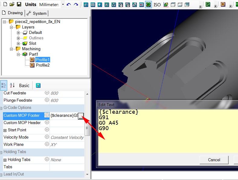
In the Custom MOP Header of the first machining operation (Profil 1) of the CAMpart Part1 we are therefore going to write:
{$clearance} >go up to the clearance plane
G91 > use relative coordinate mode.
G0 A45 > rotate axis A by 45°
G90 > return to absolute coordinates for the rest of the machining
Each time this code will be executed, A axis will rotate by 45°
In this case, the direction of rotation of the axis does not matter and you can use -45° as well as 45°
Now we are going to have to repeat the set of machining operations in the CAMPart Part1 eight times.
The idea is to use CamBam's Nesting function ; this function makes it possible to repeat all the workings of a CAMPart a certain number of times. In general, this function is used to repeat machining operations at different places on a stock.
In this case, we are going to create a repetition that reproduces the workings of Part1 always at the same place (X and Y therefore do not change) but due to the rotation GCode included in the header of the first operation, at each repetition, the A axis will first rotate 45° before the two machining operations of part1 are executed.
For this we are going to use the Points List option of the Nest Method property of the CAMPart part1. This method makes it possible to repeat the contents of the CAMPart at each position defined by a point in the point list used as a model.
As we want the machining operations to be all repeated at the same place, we simply need to create a point list containing 8 points (for 8 repetitions) whose coordinates will all be at 0,0,0 in XYZ.
Use the Draw Point List tool from the toolbar, and click once in the drawing area to create a point. (anywhere)
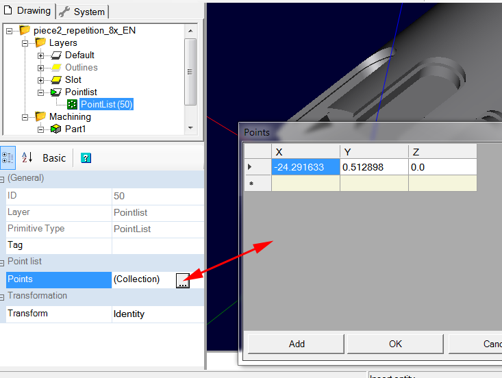
You will get a Point List object on the current layer ; select it and in its properties, click on (Collection) in the Points property, then on the |...| on the right to edit this collection.
Replace the values that are not at 0 by editing them, then click the Add button 7 times to obtain 8 lines, all at 0,0,0
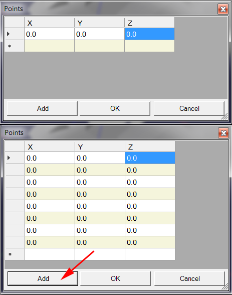
If you need to delete a row, select it by clicking in the left column and use the DEL key on the keyboard to delete it.
Click OK to finish.
We are now going to define the nesting and assign to it the Point List that we have just created.
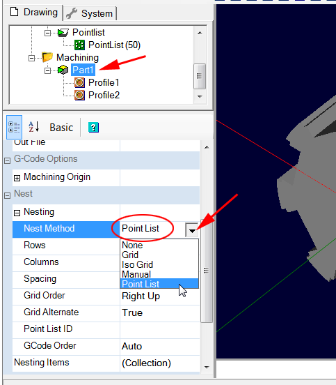
Select the CAMPart containing the operations to be repeated (part1), unfold the Nesting property and set:
Nest Method: Point List
Then, to select the Point List to use, click on the Point List ID property, then on the |...| that appears on the right, CamBam then asks you to select the list of points to use.
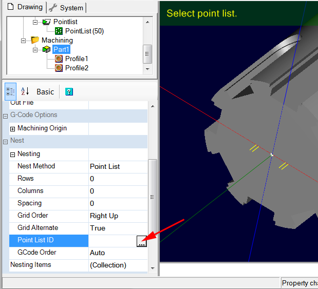
Then click on the Point List object in the list of drawing objects to select it, and validate with the Enter key on the keyboard (don't forget to validate with Enter, otherwise it will not be taken into account). In the case of this example, the Point List ID property should then contain the value 50 (the ID number of the Point List object)
You can also manually enter the ID number in the Point List ID property if desired.
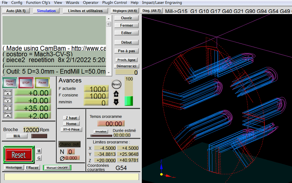
We are now done with the parameterization and we can produce the GCode and check it on Mach3 or on a 4-axis machining simulator like NCnetic for example.
Seen under Mach3
Note: if you need to create a list containing a large number of points, another method is to:
- Create a point at 0,0,0 with the Draw Point List tool (use the grid to make sure the point is created at 0,0,0)
- This point being selected, use the command Edit/Transform/Array Copy and give a value equal to number of points necessary less 1 (-1 because there is already an existing point) in Number of Copies, click on OK
- In Offset per step enter a value of 0,0,0 so that all points are created at the center of the CamBam universe.
- You will get as many Points List objects as points requested.
- With all these Point List objects selected, use the Edit/Join command to obtain a single Point List object containing all the points.
See also the documentation about Nesting.
The CamBam example file is available in the archive under the name: piece2_repetition_8x.cb
c) 2D engraving on a cylinder by wrapping the GCode
We will now move on to another 4-axis machining method ; this time, we will work with a "flat" machining, then, thanks to a specific post processor, we will produce a GCode which will "roll up" on itself ; it is in fact a question of replacing the Cartesian coordinates in X or Y by polar coordinates, the X (or Y) axis will be replaced by the A axis.
We will start with a simple, very basic engraving that will have to engrave on a 40mm diameter cylinder.
At first, we draw the design to be engraved ; in this case, my A axis is aligned with the Y axis of the machine and it is the X axis that we are going to wrap around the cylindrical shape.
Here is the drawing
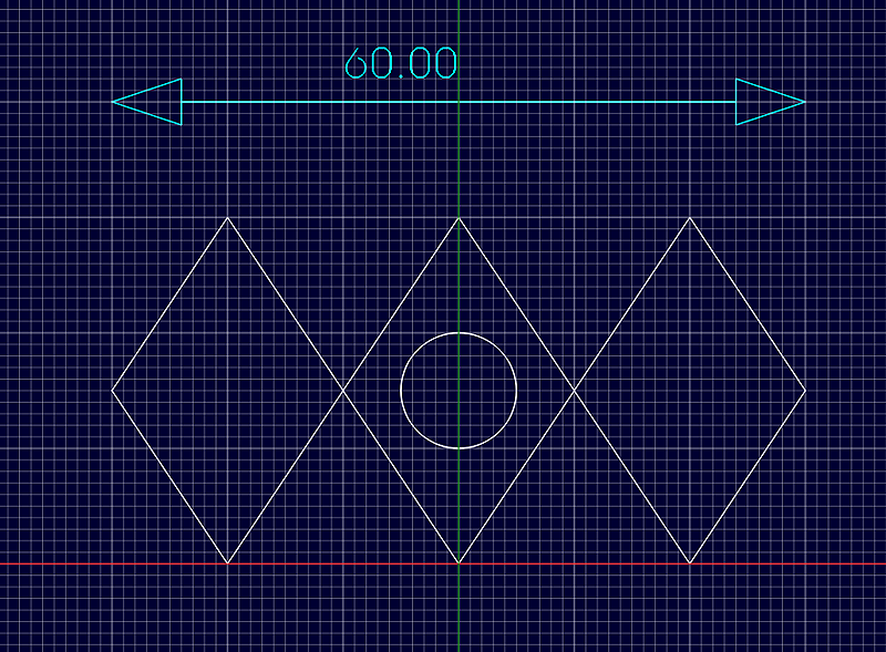
As we can see, the drawing is 60mm wide (in X therefore), and it is this X axis that will be wrapp. On a 40mm diameter cylinder, a complete "turn" would be 40 * Pi, so about 125.66 mm ; here my drawing is only 60mm, so it will not make a complete turn of the cylinder but only 60/125.66 = 0.477 times the circumference, so 0.477*360° = 171.9°
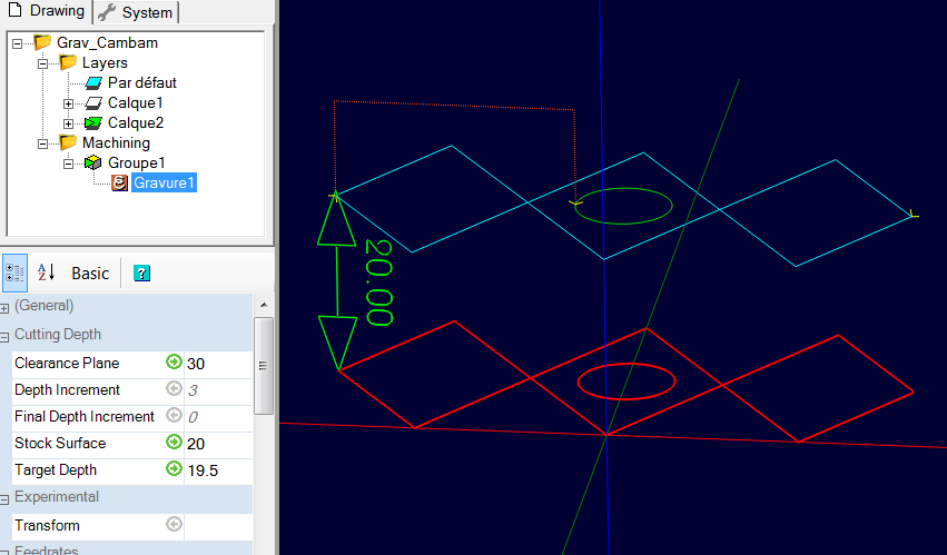
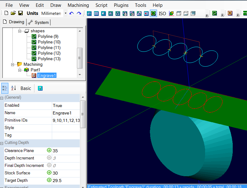
As the post processor uses the Stock Surface value as the wrap radius, we have to leave the drawing at Z=0 and set the Stock Surface value to the value of the wrap radius, here 20mm. On the image we see the drawing (in red) and the toolpaths (in blue) at 19.5mm in Z i.e. an engraving of 0.5mm depth compared to the radius of 20mm.
The work flow is quite similar to a flat engraving, except that we will select a specific post-processor for the wrapping. In CamBam V1.0, this post processor is called RotaryY for wrap X around Y, or RotaryX for wrap Y around X. In the case of this example, the rotary axis is aligned with the Y axis , so I'm going to choose the RotaryY post processor in order to wrapp X around Y.
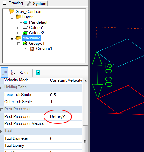
Now just produce the GCode as usual. The result cannot be simulated on CamBam, it will be necessary to examine the GCode produced on a software capable of displaying 4-axis GCode such as Mach3, NCnetic, NCplot, etc ...
Here is the result of the toolpaths seen under NCplot.
We can wrap any type of GCode, whether it is an engraving, a pocket, a profile or a 3D machining.
The CamBam example file is available in the archive under the name: grave_cylindre.cb
d) Engraving on a cone or other non-cylindrical form of revolution
It is also possible to engrave on a conical shape or any other form of revolution.
-
Engraving on a cone
The principle is the same as for engraving on a cylinder, except that the design to be engraved must be inclined at the same angle as the slope of the cone.
As for a cylinder, where the position of the drawing to be engraved must be at Z = 0 and Stock surface = at the wrapping radius, here, it is the large diameter of the cone which must be at Z = 0, the drawing to be engraved, will therefore be below Z=0.
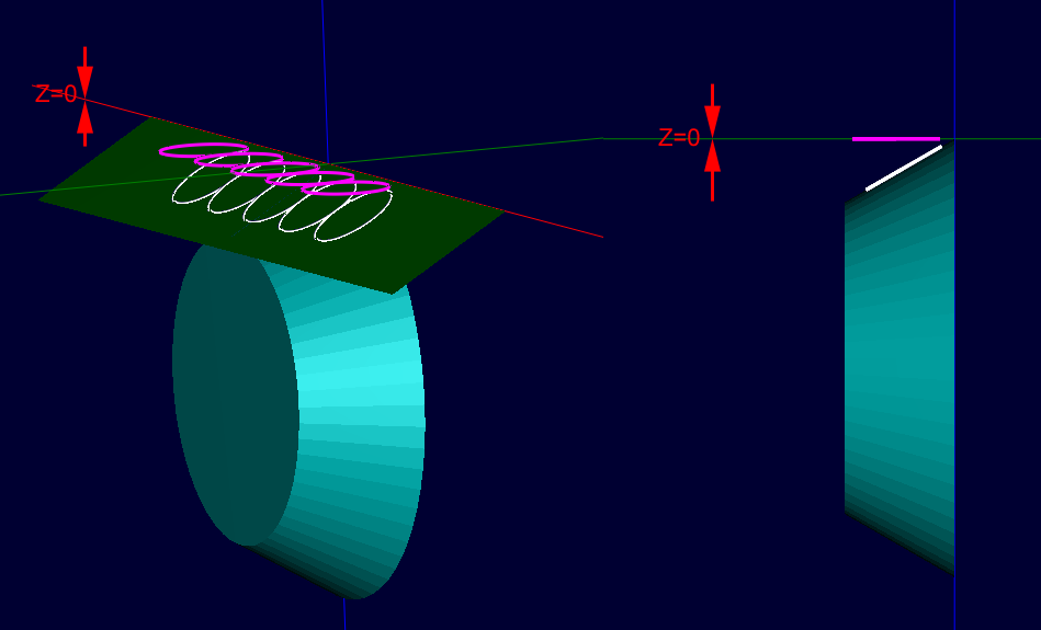
On this image, the shapes in purple have been tilted to follow the slope of the cone, which gives the circles in white ; the 3D shapes (the cone and the inclined plane) are not necessary but they help to check that everything is in the right place.
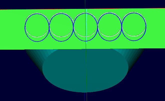
It is also possible to create inclined shapes by projecting planar shapes onto an inclined surface, however this will induce a deformation ; in the case of a projection, the inclined plane is therefore necessary. To do this, use Edit/Surface/Project Lines To Surface
As can be seen in this image, a projection of the circles (in blue) on the inclined plane produces oval shapes unlike an inclination which does not distort the drawing (in white)
As with engraving on a cylinder, Stock Surface should have a value equal to the radius. (the major radius in the case of a cone)
Only the standard CamBam engraving operation can be used for this type of machining, as it is the only one that works in 3D (a pocket or profile would only produce "flat" toolpaths and would not follow the inclination of shapes)
Don't forget to set the Clearance Plane to a value greater than the radius of the part.
The CamBam example file is available in the archive under the name: grave_cone.cb
-
Engraving on any form of revolution.
The principle remains the same, except that the projection of the drawing to be engraved will be done on a shape having the profile of the development of the final shape and not on a simple inclined plane.
After slicing the part with Edit/Surface/Plane Slice X, I keep the purple curve, which I will extrude to obtain an developed shape. CamBam can only extrude in Z, so this will require some manipulations. (you can also use my Unroll 3D Model plugin to create the developed)
I then project the drawing to be engraved on the developed.
And I use the projected lines as a design to engrave.
The rest happens as with an engraving on a cylinder/cone, Stock surface = at the maximum radius of the shape.
The CamBam example file is available in the archive under the name: grave_tonneau.cb
e) 3D machining with wrapping the GCode
As for the engraving above, wrapping a 3D model does not pose any problem and is done in exactly the same way ; the "flat" 3D object will have to be positioned at the radius and the toolpaths will be produced as for any "standard" 3D machining, it is the RotaryX or RotaryY post processor that will generate a wrapped GCode.
The only particularity in the case of a 3D model is that it will be necessary to finely manage the area to be machined using the Boundary because the machining must not "overflow" on the sides, otherwise it would make a "hole" in the part and they also need to come right to the edge of the part.
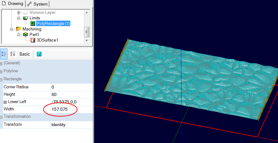
In this example, the 3D model needs to be wrapped around a 50mm diameter cylinder, and I want it to go all the way around, so I need a 3D surface of 50 * Pi = 157.075mm wide.
The top of the 3D model should be at Z=25 (the radius) ; I use the alignment tool to position the top surface of the 3D model at 25mm in Z. (the shape is centered on X, but it is not a requirement)
The 3D model is available in the archive under the name: colonne_wrap3D.stl
Positioning of the upper face at Z = 25
As seen in the following image, the toolpaths should stop right at the edge of the 3D model (red arrows)
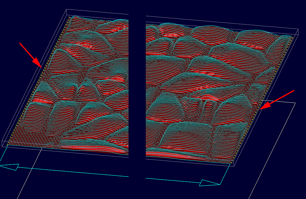
To make sure that the toolpaths will not down on the sides of the model, which would produce a hole in the part, or that the toolpaths will not stop before the end of the model, which would leave an unmachined area, I uses a rectangle of the exact width to be machined, here 157.075, which will be used as the machining limit.
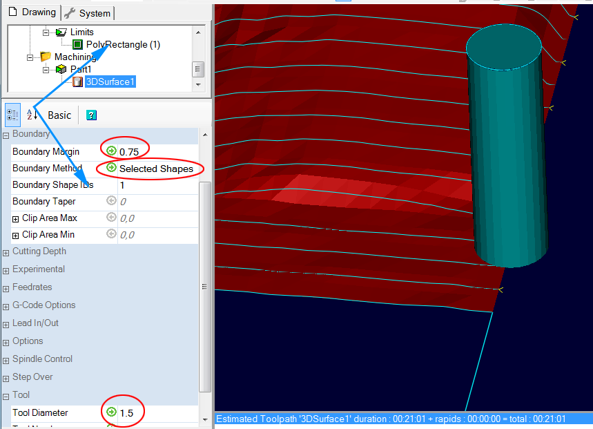
In the Boundary, I set Boundary Method to Selected Shapes, use my rectangle (Rectangle1) as Boundary Shapes IDs, and set Boundary Margin to a value equal to the radius of the tool being used ; here my tool is 1.5mm in diameter, so I set my Boundary Margin to 0.75
Why add tool radius? ....because CamBam manages the boundaries in such a way that the tool stays inside the boundaries, therefore the toolpaths stop at a distance equal to the radius of the tool from the boundaries.
On this image, with Boundary Margin to 0, we see that the toolpaths do not reach the end of the model bounded by the rectangle used to define the limits.
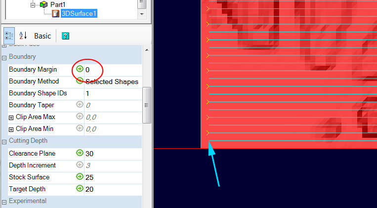
The goal is to ensure that the center of the tool arrives exactly at the end of the boudary shape, no more otherwise we go down the sides, but no less otherwise the model will not be machined to the end.
With Boundary Margin equal to tool radius, the center of the tool comes right up to the boundary of the model
Now all that remains is to produce the GCode, of course using a RotaryY post processor in this case.
The example CamBam file is available in the archive under the name: colonne_wrap3D.cb
In the case where the 3D object is not a developed shape, you must use my Unroll 3D Model plugin to obtain the unrolled shape, the rest of the procedure is then identical to what we have just seen with the 3D "stone texture" above.
Here, it is the unrolled shape in red that would be used to produce the GCode.
The scanline direction (horizontal/vertical) of the 3D profile operation will determine whether the shape is machined by turning, or by parallel strips along the axis of rotation.
To save time during machining and avoid tool returns in the air, it is a good idea to set the Milling Direction to Mixed.
Rotating machining
Strip machining
++
David