V-Engrave
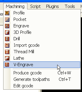
The principle of this machining operation is to cut between two lines forming a "limit" while maintaining the edges of the V cutter in contact with these limits. The V-Engrave operation will therefore vary the machining depth to achieve this purpose.
After selecting a closed shape, use the Machining menu to create a V-Engrave operation.
Then complete the properties of the machining operation.
If you want to engrave the space between two closed polylines, you must first convert the set of polylines to a Region.
To do this, select the two polylines and use the menu: Edit/Convert to/Region (Ctrl + i)
Engrave a Text object: The V-Engrave operation can be applied directly to a Text object if it maintains its horizontal position. If the text has to be tilted, it will have to be exploded (only once) to obtain Regions, which can then be used with a V-Engrave operation.
The array below only lists the properties specific to this operation
Properties
Tool |
|
| Tool V-Angle | Angle of the V-cutter Note: For this operation, the tool must be a V-Cutter |
Tool Diameter |
Tool diameter (in drawing units) Maximum diameter of the top of the V of the cutter. This value will allow the plugin to calculate a maximum machining depth so as not to go lower than allowed by the V of the cutter. This value is used to do calculations if Max Depth is set to Auto |
| Tool Tip Diameter | If the cutter has a flat end, this diameter corresponds to the diameter of the tip. |
Cutting Depth |
|
Depth Increment |
Depth increment of each machining pass. Determines the number of passes to reach the final target depth. |
Max Depth |
Limits the maximum depth of machining. This value is a positive value representing the maximum depth to be reached. If this parameter is set to Auto, the maximum depth is automatically calculated so that the cutter does not go down lower than allowed by the V. (using the diameter value of the tool for calculations) |
| Stock Surface | The Z starting point for the cut. The plugin works as the Profile/Pocket operations, the Z position of the drawing is unimportant; the cut starts from Stock Surface. |
Options |
|
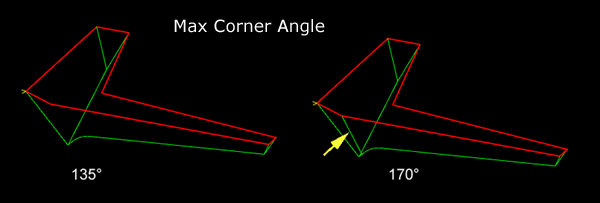
Max Corner Angle |
Maximum angle for the corners where a ascent of the tool will be added . If the angle and larger than this value, no ascent of the tool will be generated.
|
Path Step Size |
Length of the steps in the toolpath. For work in mm, a value of 0.1 gives a correct resolution with a reasonable calculation time. |
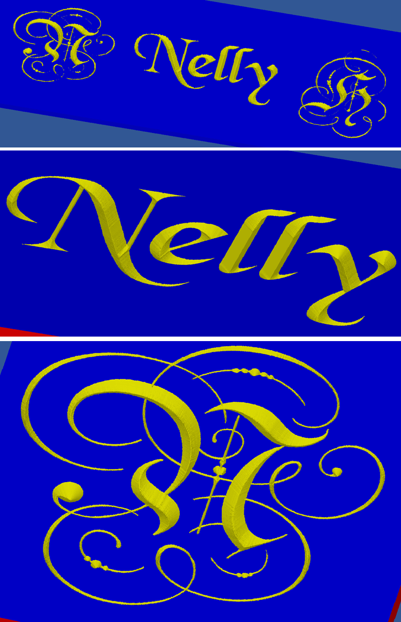
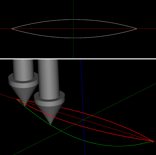
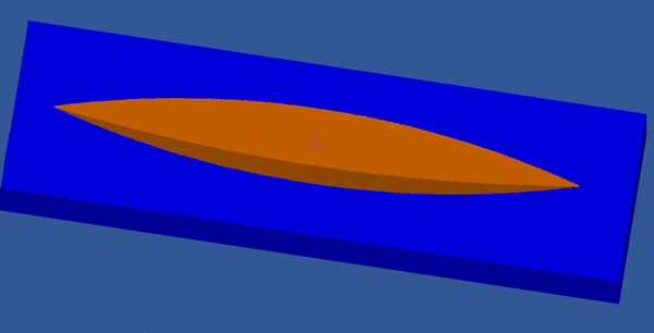
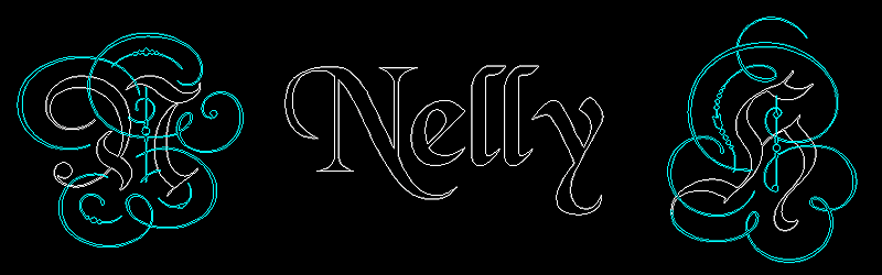
An example of the result on texts and logos.
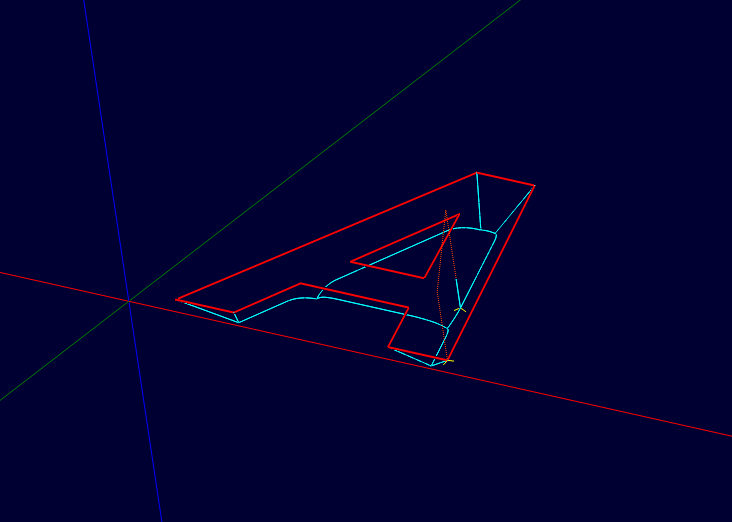
The drawing seen in CamBam
Some views simulated with CutViewer Mill.
Two V-Engrave operations are used ; the first operation using a 90° V-cutter for the shapes in white on the drawing , the second operation using a 60° V-cutter for machining the shapes in blue on the drawing.